Replacing clock wheel teethby Alf Wilford, Australia
Download a pdf of this article
Believe it or not, the owner of the carriage clock shown in figure 1 bought it for five dollars! He was a bit doubtful as to whether it was a genuine one or a cheap copy, and as it would not run for more than a few hours at a time he decided to take it apart to see if he could find out what was the matter with it. He did not get very far before he realised that this was not a cheap copy but the real thing, so he handed it to me to have a look at and assess its possibilities. Having bought it so cheaply he was prepared to pay for a repair that would enable him to sell it for a profit.
When I dismantled the clock, I found that the intermediate wheel was missing two adjacent teeth. I had seen this situation before with French clocks: the intermediate wheel sometimes suffers damage, rather than the barrel teeth, as a result of a winding accident or a mainspring breakage. A decision had to be made as to how to repair the wheel: this was not a sturdy wheel like the great wheel of a longcase clock, and the rim was not very wide. I did not want to cut a recess for a dovetailed insert as I thought this could weaken the wheel. An insert silver soldered in place would involve a risky procedure with such a small wheel.
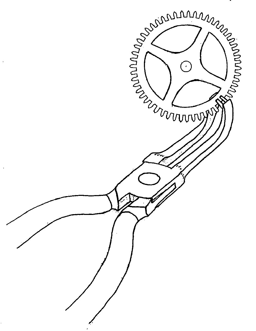
I eventually decided to make two cuts with a piercing saw and to file recesses to insert two separate teeth, leaving solid brass between the recesses, reasoning that this bit of solid brass would retain some of the strength of the wheel rim and also provide enough surface area in the joint for soft solder to lock the inserted teeth firmly in place. The brass inserts were carefully filed until they would be a tight fit in their respective recesses. They were pressed in place with the aid of a pair of pliers with offset jaws, figure 2. Pliers of this kind are useful for tasks like this because the jaws remain parallel to the axis of the hinged joint, particularly so when a good pair of box-jointed pliers is available.
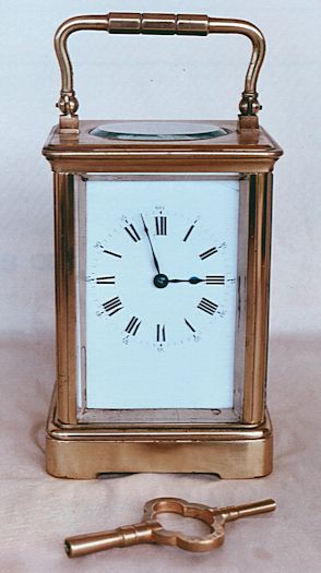
A spirit lamp was used to soft solder the inserted teeth in place. The strength of such a repair depends on the mechanical strength of the inserted teeth being a tight press fit in their recesses; the soldering is done only to lock the teeth in place. The inserts were then filed flush with the rim of the wheel and the tooth profiles formed with needle files. Then the repaired area was smoothed with a Water-of-Ayr stone, polished with Wenol metal polish applied with a bamboo splint, and brushed with lacquer to match the wheel’s original finish.
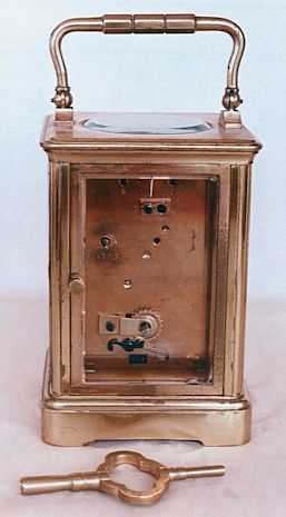
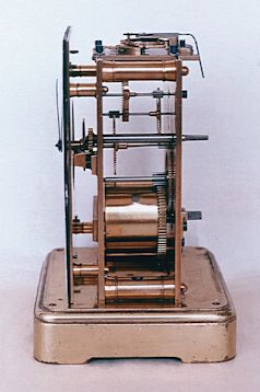
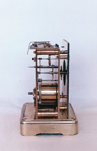
This clock does not have the usual cylinder escapement: it has the type of lever escapement seen in English key-wind fusee watches of the Victorian era. W.J Gazeley in Watch and Clock Making and Repairing refers to this type as the ratchet-tooth escapement. This raises the question as to whether this is a French carriage clock or an English one. Perhaps it is both? Perhaps the lever escapement was put in to replace an original cylinder escapement in Victorian times? Figures 3, 4 and 5 are other photographs of this timepiece.
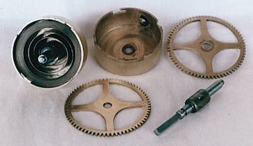
Another repair of a similar nature was needed for a H A C mantel clock. The mainspring of the going train had broken while the clock was being wound, I was told. Figure 6 shows how the spring barrels and great wheels of this clock are held together in bayonet fashion, making it easier to attend to mainsprings. When the mainspring had broken, two teeth of the great wheel had also broken. It was decided that a brass insert silver-soldered in place would be the best way to go in this situation, where the replacement teeth would have to withstand the load of a fully wound mainspring.
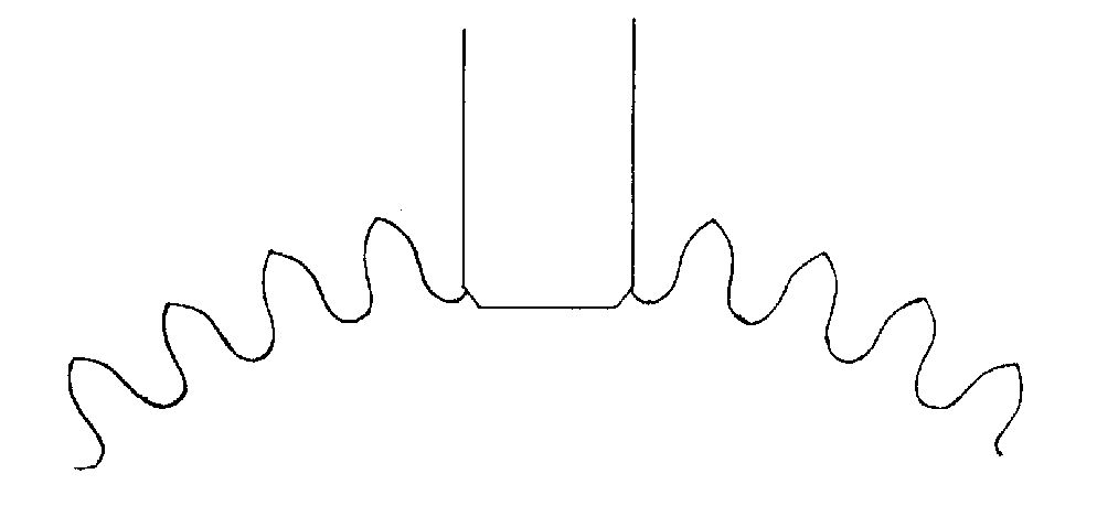
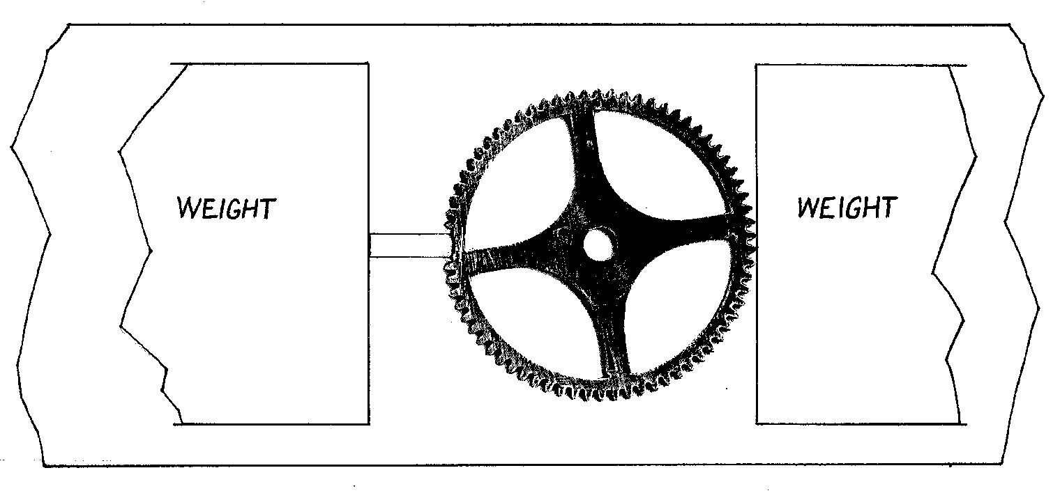
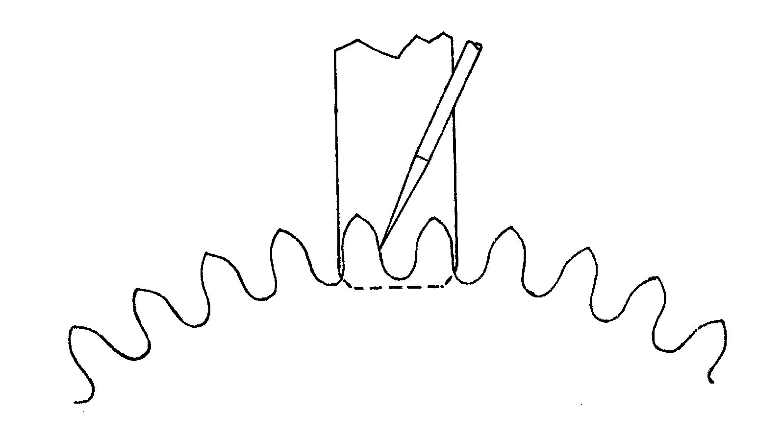
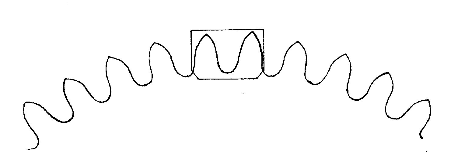
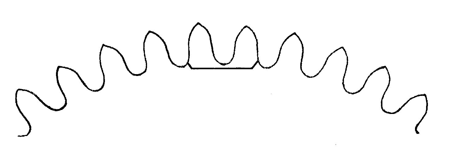
The rim of the wheel again was rather narrow and would be weakened by a dovetailed insert soft soldered in place or by separate replacement teeth pressed into place and locked with soft solder. A brass insert was therefore prepared and fitted to a shallow recess filed in the wheel rim, figure 7. Then the wheel and the insert were positioned on a piece of fire-brick, paste silver soldering flux being pressed in the joint as it was assembled, and the two parts held in place by heavy cast iron weights, figure 8.
Small cut pieces of silver solder were placed on the joint and heat was applied with a Primus Handyman propane torch fitted with a pinpoint burner. When a fine line of silver solder ran around the joint the heat was removed and the job allowed to cool. Then the striking train great wheel was placed over the wheel being repaired and used as a template to mark outlines with a scriber on the insert for the replacement teeth, figure 9.
Figure 10 shows the marked insert, with the excess brass sawn off, ready for the teeth to be formed, and figure 11 shows the teeth filed to shape. Finishing was done as for the previously mentioned repair job, and the assembled barrels and great wheels are shown in figure 12, the new mainspring being fitted to the striking train barrel rather than to the time train barrel. It is generally accepted that the stronger spring of the two should be fitted to the striking train rather than to the time train.
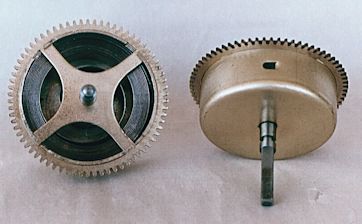
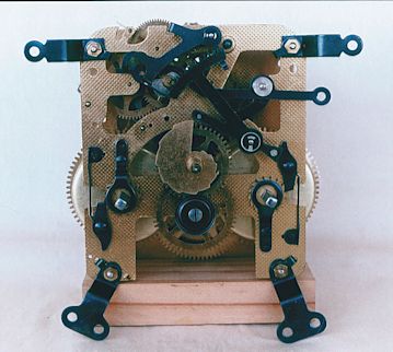
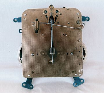
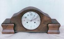
Figure 13 shows the front of the assembled movement and figure 14 shows the back of it. The repaired clock is shown in figure 15.
When one goes to the dentist, decisions have to be made: amalgam filling or ceramic/polymer filling; extraction or root canal treatment, and so on; including, of course, cost considerations! So it is with clock wheel teeth repairs, but such decisions are easier to make when they don't involve the inside of one's own mouth!
Download a pdf of this article
|
| © 1977 to 2015 Clocks Magazine & Splat Publishing Ltd |
|

