Replacing clock calendar wheelsby Dennis Haynes, UK
Download a pdf of this article
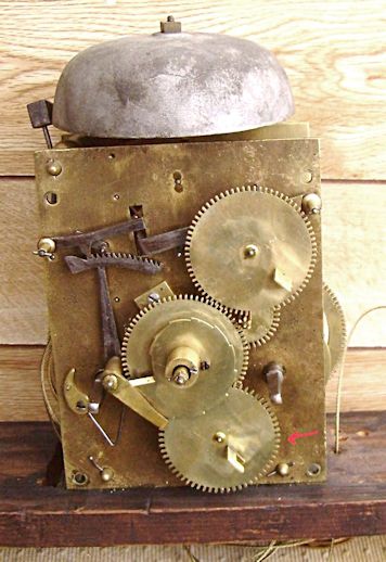
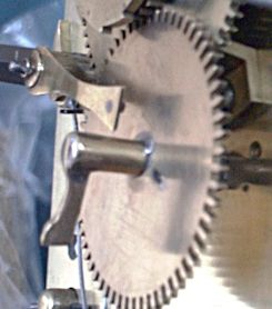
I wonder if restorers who handle brass-dial longcase clock movements are as amazed as I am by how many are missing their calendar-drive 24-hour wheels. For those who donít know, I refer to the wheel that takes the drive from the hour pipe and tips the calendar ring round by means of a pin or flag on its outer surface. A movement with the wheel and its flag intact is shown in figure 1 and the ring that it turns is shown in figure 2.
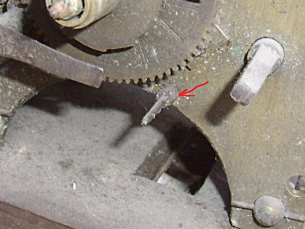
I would think that easily half of the movements I have encountered over the years have this wheel missing, a typical example being shown in figure 3. It seems that the old clock repairmen were united in their desire to convince the public that the calendar facility was not necessary and that its presence was detrimental to the running of the clock. Whatever the reason, there must be an enormous cache of these wheels somewhere.
Replacing the wheel is well within the scope of the amateur restorer particularly if the mounting stud is still in place. Even if it is not, the threaded hole to take it will still be there.
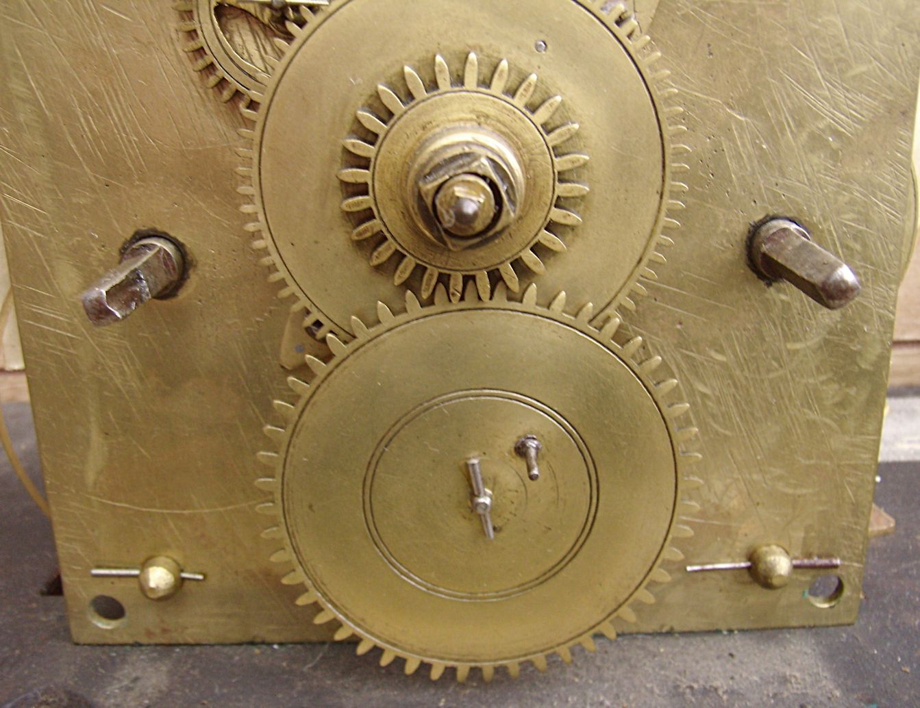
The wheel is driven by a gear wheel on the hour pipe that on countwheel strike is open to view, figure 4, and on rack strike is behind the snail, figure 1. As the hour pipe rotates once every 12 hours, to get a 24-hour rotation we need a two-to-one step down. Then it is a simple matter to measure from the mounting stud to half the depth of the teeth on the hour pipe (itís called the addendum), double it and we have the diameter of the new wheel we need. These wheels are readily available from specialists such as Michael Debenham and Peter Holtby who advertise in this magazine. These individuals will also supply the collet to mount it and the pivoting stud if this is missing.
Positioning the flag on the wheel to operate the numbered ring can be a little tricky and Iím sure every restorer has his or her own way of arriving at the correct position. My own method, for what it is worth, is to place a piece of Blu-tac on the back of the dial in approximately where the mounting stud comes, offer the dial on to the movement and note the depression left in the Blu-tac by the end of the stud. A measurement is taken from the depression to the root of the teeth on the date ring and the operating flag fitted and filed back by trial-and-error until it presents the numbers centrally in the aperture when the wheel is turned. When carrying out this procedure, I find it best to take off the rest of the motion work so that the 24-hour wheel can be pushed round easily with the fingers.
One sometimes sees a pin fitted to operate the ring and while this can be perfectly adequate; I like to use a flag myself. They can be slotted into the wheel and riveted over to provide a more secure fixing. In fact, in some cases, a flag is the only way because with rack striking, a step has to be cut in the flag to allow clearance for the rack tail, figure 1. To provide maximum clearance for the rack tail, I have in the past fitted the operating flag in the end of the wheel collet so that it almost buts up against the dial plate and in addition to the increased clearance also restricts the end float and does away with the necessity for a fiddly pin hole in the end of the mounting stud, figure 5.
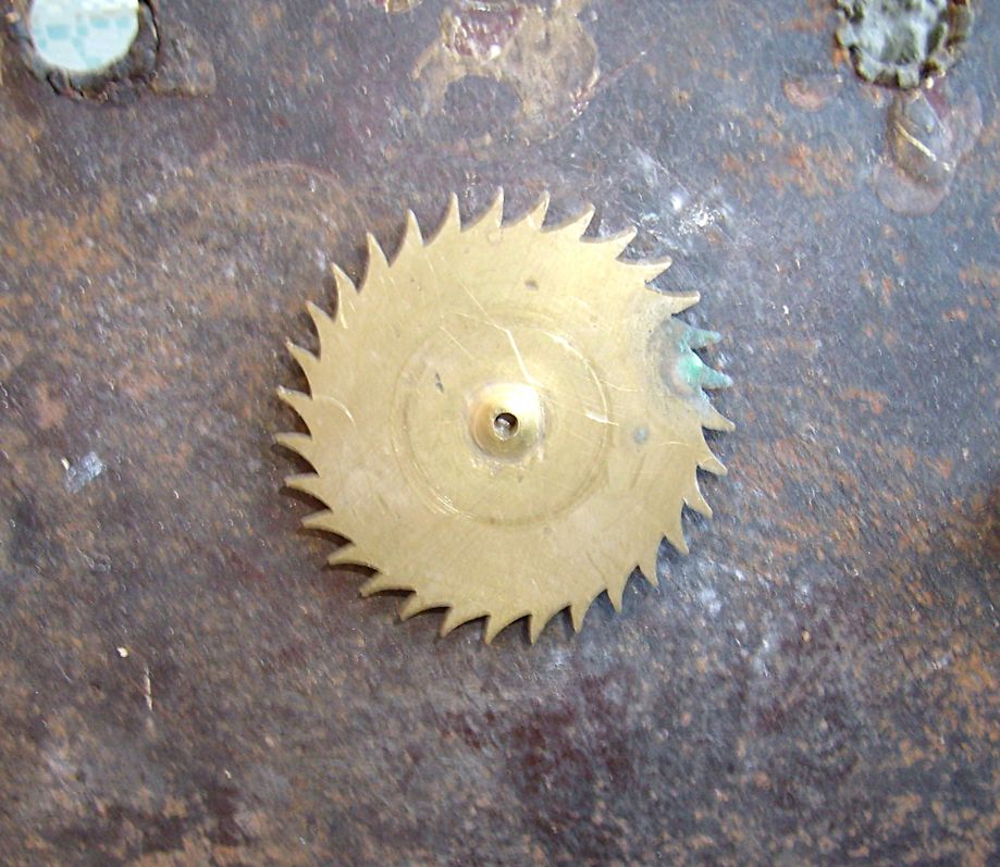
For the movements that use a pointer instead of a calendar ring, the procedure is exactly the same The only difference being that instead of turning a ring, the pin tips round a little 31-toothed wheel, figure 6. In this case, I think a pin is more appropriate than a flag.
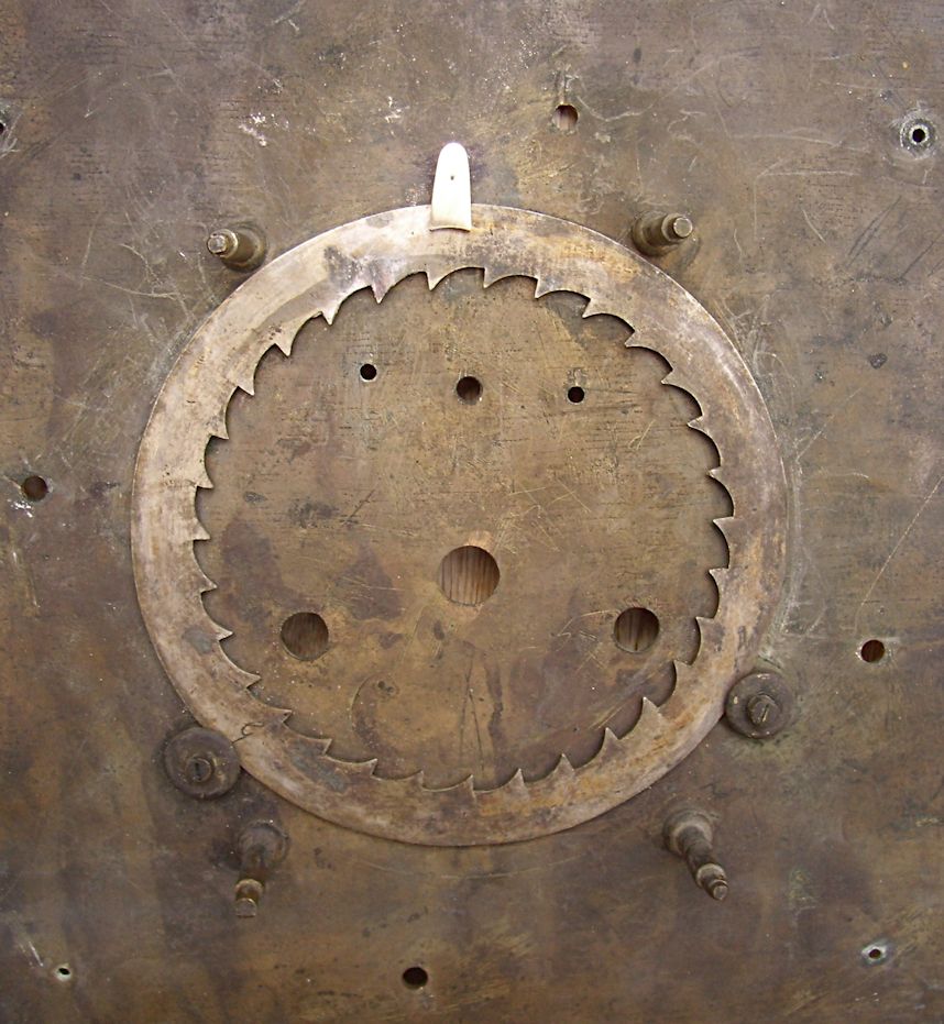


So far this repair is relatively simple, but it becomes vastly more complicated if the calendar ring itself is missing. Before proceeding further, it may be as well to describe how the ring is fitted when the clock was originally made. The clockmaker makes the movement and then inserts a blank ring in position in the dial. The movement is then put through a monthís sequence and for each day; the dimensions of the aperture are scribed on the ring through the front of the dial. The ring is then sent to the engraver for each day of the month to be engraved in the scribed apertures. This procedure means that each ring is unique to the dial and movement for which it was made.
If the ring is missing, the restorer is faced with a dilemma. The obvious course is to provide a new blank ring and go through the procedure described in the previous paragraph but this can be expensive. The rings and engraving are readily available from specialist firms such as Goodacre Engraving but the overall cost will be at least £100 and the restorer may feel that the value of the movement does not warrant this outlay.
Spare rings are also available and are frequently seen on Ebay, at auctions and clock fairs but using one of these can involve problems. The first step obviously, is to obtain a ring of the correct diameter and they do vary from 4.5 inches (115mm) to 6.5 inches (165mm). Once the restorer has a ring of the correct diameter, he may be lucky and find that it works correctly but more than likely it will be found that the numbers do not present themselves in the centre of the aperture. Bending the flag a little may help but experienced restorers will know that solutions like that rarely occur. In that case, the only remedy is to move the pivot pin and change the position of the 24-hour wheel and potential restorers may be interested in how I overcame such a problem quite recently.
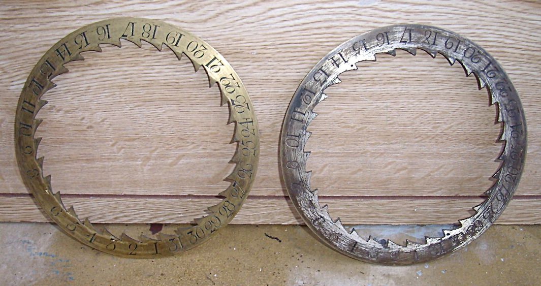
When the movement came to me, the calendar ring behind the dial was an obvious and incorrect replacement, figure 7. It was too narrow and did not cover the aperture in the dial plate. The god of clockmakers smiled on me and I was fortunate enough to find a better replacement in the spares box, figure 8. The old one is on the left, the new one on the right. However, my good luck finished there and when put through its paces, the numbers on the replacement ring did not come in the centre of the aperture and the only solution was to move the 24-hour wheel. Examination of the movement front plate revealed that a previous restorer was aware of this but his attempts to correct the problem using the narrow calendar ring had proved unsuccessful, as it has to be said, they were bound to. The front plate, in addition to several holes, had also been plugged in two places, figure 9, so he could not be condemned for lack of effort.
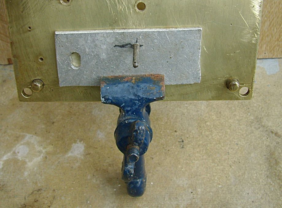
To establish the correct position for the wheel pivot, I had to work backwards. Firstly, the existing holes were plugged. Then a piece of plate was tapped and fitted with a pivot stud and clamped to the front plate, figure 10, and the wheel dropped on. The dial was offered on to the movement with the calendar ring in position and the plate moved until the numbers were central in the aperture when the wheel was turned. The position of the stud was noted and the front plate drilled and tapped to take it.
I hope readers will be amused to learn that I got it wrong the first time and the stud was 1mm too high and the wheel would not mesh. Luckily, the hole came dead in the centre of one of the plugged holes and I was able to knock it out, replug and tap a fresh hole. This repair proved successful but it was time-consuming and I would ask potential customers to bear this in mind when they are quoted what they feel are exorbitant prices by professional restorers.
This kind of repair is one of many faced regularly by professional and amateur restorersóthe sort that can usually be overcome with a modicum of good luck and a little ingenuity.
Download a pdf of this article
|
|
