Repairing a clock dial pillaarby Ian Beilby, UK
Download a pdf of this article
Taper pins provide a quick and reliable means of holding together clock plates and dials. They are also used to retain various other components in place on clock movements. If fitted and used correctly they provide for a swift and efficient means of assembling and dismantling a clock movement.
You can, however, have difficulties with them. It is not uncommon to find that they can be very difficult to remove, especially if they have not been fitted correctly or damaged in use over the years. One of the commonest problems is if they have been cut off too short. This can make it very difficult to obtain sufficient purchase and remove them easily. Badly mauled pins should always be replaced with ones of the correct size and type. The pins should be left with sufficient length in order for them to be easily removed if necessary in the future.
The pin should enter the hole in the spigot and the taper start to bear on the plate when approximately a third of the way through the hole. When fully pinned-up the taper pin should be roughly halfway through the spigot.
If a pin with too small a taper is used there is the risk that the pin will be ineffective and eventually fall out, conversely too large a pin will not enter the hole sufficiently and may burst the spigot hole if too much force is used. This again is a common problem and you frequently encounter movements and dials with pillars that have been damaged through the miss-use of taper pins.
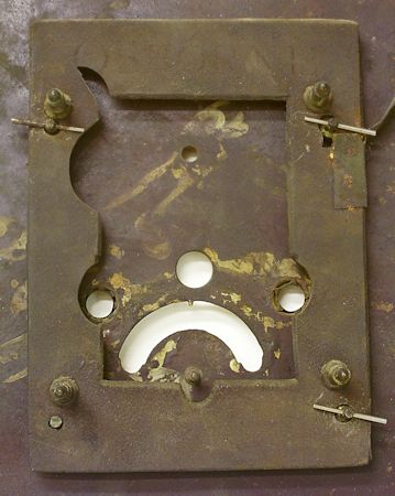
The dial shown in figure 1 is a typical longcase moon roller dial from the 1820s. You can see the Osborne falseplate attached to the back of the dial and the absence of a taper pin in the lower left-hand dial pillar.
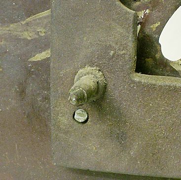
The close-up in figure 2 reveals the reason. The hole in the spigot of the dial pillar has burst at some time in the past and it is now no longer possible to attach the dial to the falseplate efficiently. Although the other pillars are undamaged, all four pillars should attach these heavy dials if they are to be positively located to the movement. Not only does this retain the dial in place correctly and prevent movement, but also evens-out the stresses on the dial preventing further damage.
You can see in figure 1 that the pins used to attach the falseplate to the dial are quite substantial and if too much force is used when inserting the pins they can easily damage the spigots. In order to repair the dial pillar a new spigot would have to be made and fitted to the dial pillar.
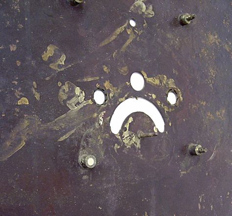
I decided to machine a threaded spigot to match the existing hole in the falseplate and drill and tap the dial pillar. The spigot hole in the falseplate was just under žin so one end of a length of žin brass rod was machined to fit and the other end threaded 5 BA. The dial pillar would have to be drilled centrally in order for the spigot to be correctly located and screwed into the pillar. The damaged spigot on the dial pillar was filed off as shown in figure 3.
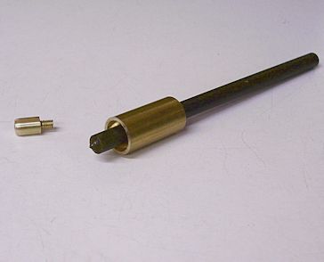
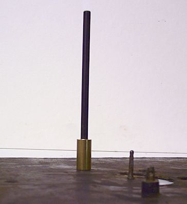
It may well have been possible to simply centre punch the dial pillar by eye and drill and tap the pillar, but I wanted to ensure accuracy as much as possible and so I made a simple bush to locate on the body of the pillar. The bush was also provided with a žin hole into which I could insert a žin diameter centre punch. The bush, centre punch and spigot are shown in figure 4.
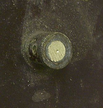
The bush and centre punch were placed onto the dial pillar as shown in figure 5 and the centre punch given a sharp tap with a small hammer. This method ensured accuracy and ensured that the spigot when fitted to the pillar would line-up correctly with the hole in the falseplate. Figure 6 shows the pillar with the centre dot clearly located in the centre of the pillar.
The dial was then taken to the drilling machine and the dial pillar drilled with the correct 5 BA tapping drill. Naturally great care has to be taken to ensure that the dial pillar is only drilled for approximately two-thirds of its length, under no circumstances must the drill be allowed to pierce the front of the dial.
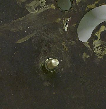
With the dial pillar successfully drilled the hole was then tapped 5 BA. The spigot was then screwed fully into the dial pillar as shown in figure 7.
It was then possible to replace the falseplate and determine the position of the cross-hole for the taper pin. With the falseplate in position a fine hand-held slitting saw was used to mark the position of the cross-hole.
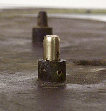
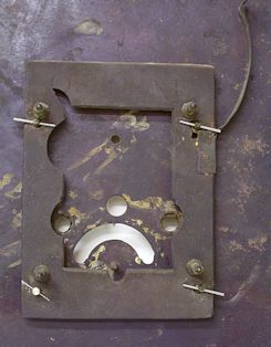
The spigot was unscrewed from the dial pillar and held in the machine vice in order to drill the cross-hole. It was then replaced in the dial pillar as shown in figure 8 and a check made to ensure that with a taper pin in place the falseplate pulled up tightly to the shoulder of the dial pillar.
When happy with the fitting of the spigot and taper pin the spigot was unscrewed and a couple of drops of loctite applied to the threads before tightly screwing the spigot into the dial pillar. The pinned-up false plate is shown in figure 9.
Readers will notice that I have deliberately fitted a smaller taper pin to the repaired dial pillar. In my opinion the other pins are far too large for the diameter of the spigots and this may well have been a contributing factor to the damage caused to the repaired pillar.
Download a pdf of this article
|
|

