Renovating clock pulleysby Dennis Haynes, UK
Download a pdf of this article
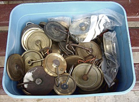
While browsing idly through Ebay one day I came across a box of longcase pulleys offered for auction, figure 1. Spare pulleys are often useful so I decided on a speculative punt and to my surprise and delight, I was successful.
When the box arrived I was even more pleased. The box contained both 30-hour and eight-day pulleys, some of the eight-days in matching pairs and some not, some with stirrups and centre pins and some not. There were even two nice 30-hour boxwood pulleys.
In the feedback I get from previous articles, I am very often asked to describe the simple and basic things so if our more experienced readers will bear with me, I will briefly explain the difference between eight day and thirty hour pulleys.
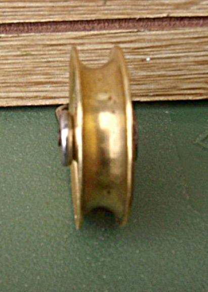
There are two different 30-hour pulleys, those for rope and those for chain. The rope pulleys have a continuous semi circular groove round the outside of the rim to take the rope, figure 2. Ropes come in 6mm, 7mm and 8mm diameters and the size the clock needs is dictated by the width of the driving pulleys. The rope pulley must be chosen to suit. Some are wider than others to take different diameters of rope but in the main will usually take most diameters but it is something that should be considered when making a selection.
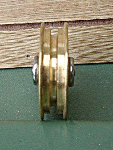
The rope pulley will quite happily take a chain and will often need to when a chain conversion has been carried out on the movement. The chain pulleys are the same but have a channel down the outside rim of the pulley to take the intermediate links of the chain, figure 3. I suppose they would take a rope if pressed but it is not advisable and doesn’t look right.
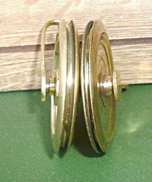
Eight-day pulleys are completely different being much thinner with a narrow groove round the rim to take the gut line and, of course they come in pairs, figure 4.
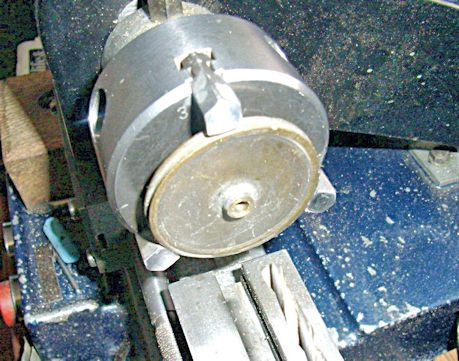
Finding myself with a day or two to spare between jobs, I decided to go through the pulleys and restore those that were in need of it. There were seven 30-hour rope pulleys all missing their stirrups and centre pins so I made a start with these. Each pulley was set up in the lathe and the centres taken out to a true round with either a drill or the boring tool, figure 5. At the same time the opportunity was taken to use the lathe speed to clean and polish them.
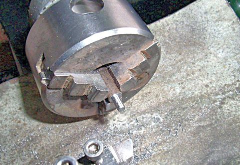
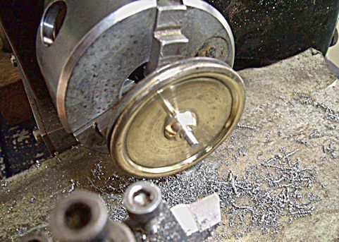
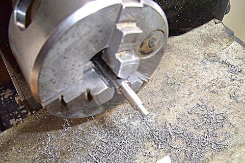
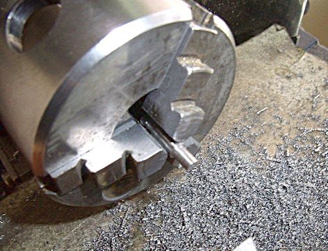
The centre pins were turned in three stages. The first stage, figure 6, is to turn an end stub to 3mm or thereabouts for entry into one end of a stirrup. The next stage is to advance the stock in the chuck and turn the centre portion to suit the pulley centre. This obviously has to be done to suit each individual pulley centre diameter and is worth taking some trouble over. The pin should be carefully turned until the pulley will nearly screw onto the pin and then finished off with progressively fine papers until the pulley is highly polished and is a running fit on the pin, figure 7. The pin can then be sawn off, reversed in the lathe and the other end turned to fit into the stirrup. Stages two and three are shown in figures 8 and 9.


The steel used for the centre pins can be either mild steel or silver (tool) steel. Every restorer will have his own ideas on the subject. To my mind it makes little difference. If tool steel is used, it can be hardened and tempered and will suffer little wear in use and all the wear will take place in the pulley itself. If mild steel is used, both centre pin and pulley will wear equally. In any event, whatever happens, if the repair is made correctly, we will all be long gone before it needs doing again.
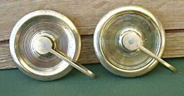
Where the pulleys already have their stirrups and only the centre needs restoring, the pin can be removed by simply driving it through, spreading the stirrup and releasing the wheel. Steel stirrups spread quite easily but brass ones are brittle and often break. They can be repaired quite easily by annealing the two broken pieces by bringing them to red heat and quenching in water and then repairing the join with silver solder. The annealing process will make the brass quite pliable and the stirrup can be easily bent back into shape.
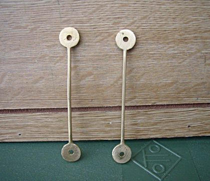
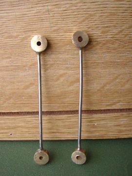
When new stirrups have to be made, every restorer will again have his or her favourite method and there is any amount to choose from. I use two. The first is where the stirrup is cut straight out of a strip of 1.5mm or 2mm brass, figure 10, and then bent to shape, but my own favourite is as follows. A length of 10mm brass bar is set up in the lathe and a 3mm hole drilled down the centre.
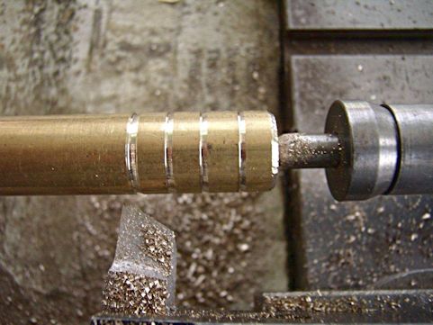
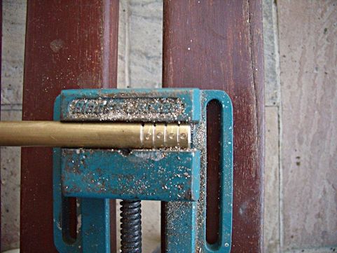
A lathe tool is then used to make cuts about 5mm apart down the length of the bar and a centre dot made in the centre of each division, figures 11 and 12. The bar is taken to the pillar drill and a 2mm hole drilled into each division using the centre dot and then each division is parted off. To link the two divisions together to make the stirrup, a piece of 2mm iron wire 65mm long is snipped off , the ends inserted into the previously drilled holes and silver soldered in place, figure 13. The piece is then bent round to form the stirrup, the ends of the pins inserted into the 3mm holes and riveted over and cleaned up, figure 14.
The seven 30-hour pulleys without centres mentioned earlier are shown in their restored state in figure 15, while figure 16 shows several eight day pulleys in the course of restoration. These are shown completed in figure 17.
Download a pdf of this article
|
|

