Making a grandfather clock caseby Clive Pickering, Australia
Download a pdf of this article
This story began with an evening phone call from a well-respected clock restorer from Sydney. He was enquiring if I was still interested in building cases for clocks. Apparently he had been commissioned to restore a painted dial longcase movement and the lady owner of the clock was extremely keen to have a traditional style case built to house her movement.
He went on to say that the owner was an extremely nice and genuine lady who had an interesting tale to tell about her old clock movement. Apparently she was quite willing to come and meet with me and relate this story. I reasoned that if she was prepared take the time and effort to travel the significant distance to meet me from her home in Sydney the least that I could do was be gracious enough to invite her to visit.
The day for the scheduled visit arrived and after introductions and pleasantries had been completed I gave Belinda a tour of my clock collection that, she had informed me over the phone, she was rather keen to view. We chatted easily and it soon became quite apparent that she was rather passionate about old clocks. Belinda had arrived bearing low calorie ‘sticky buns’ for our morning tea and it was during the morning tea break that she related the rather interesting story of her clock.
In 1861 Belinda’s great-great grandfather William Crawford (born in February 1825 in Portglenone and raised on a farm in Ballynease) had migrated from Ireland to Australia and had brought with him his most treasured possession, a painted-dial moon-phase longcase clock movement by Samuel Brown of Maghera. Because of the costs of shipping and the space the case would have required it had been left behind in Ireland. On arrival, and after settling in, the movement had been re-housed in a large and featureless home built Australian red cedar case. The treasured clock had been passed over the years, down through the family and Belinda had become its present custodian. The clock had stopped and Belinda had made the decision to have it returned to working order.
It was during her conversations with the clock restorer that she mentioned her desire to have a more appropriate period style case constructed for her old clock movement. The restorer, whom I have known for many years, then made mention of my particular penchant for re housing orphaned clock movements.
Belinda showed me pictures of the clock’s present case and I admit to being rather torn between my desires not to interfere with the obvious history of this old clock and to give it a more appropriate home, figure 1. Though the clock movement had resided in this present case for approximately 150 years the case did absolutely nothing to enhance the beauty of the old movement. Added to this the rather worn and faded dial of Samuel Brown was also going to be restored.


Belinda made it apparent that she very much liked my work and the way that I presented my re-housed movements. We discussed the costs and time involved in a case build and by the end of the most pleasant visit I promised to design for her a case I felt would be suitable for her movement. Belinda expressed her desire for a case to be built similar to the one that William had probably left behind in Ireland. One other significant factor was that her timber of choice for the new case was to be the same as the present case and indeed my favorite timber … Australian red cedar.
After consulting the texts I made a full-size drawing on to a sheet of MDF of a case that I felt would suit the movement, figure 2. By the very nature of the movement the case would, by necessity, be on the plain side. This fact had been mooted during earlier discussions on the design of the new case. I emailed the case design photographs to Belinda. Conformation arrived that she liked the design and the project was able to begin.
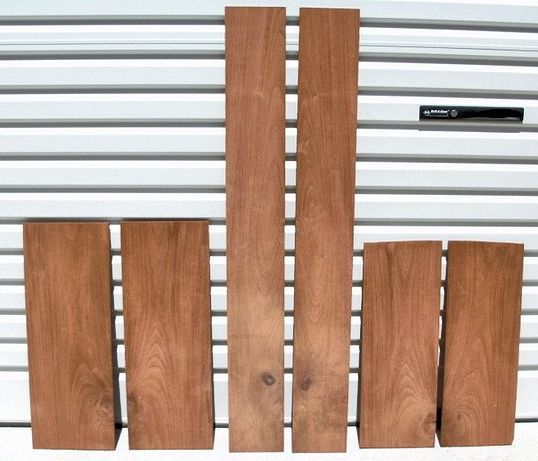
A length of nicely grained cedar timber was chosen for the sides of the case. I cut this into three sections: one for the hood, one for the trunk and one for the base. This would ensure a continuity of grain flow down each side of the case. Each section was then split along its length by first passing it over my table saw with the blade raised to maximum height. A guide fixed to the saw table ensured the sections were cut straight and down the centre. Once cut, the section was then rotated lengthwise and the procedure repeated. A handsaw was used to finish cutting each section into book-matched pieces.
Australian red cedar timber darkens as it ages and therefore it affords a nice contrast when using older figured cedar for a feature panel. To this end I selected sections of aged cedar from which I would feature on the base panel, trunk door and the hood door. These were reduced in thickness to 5mm.
When the sections had been passed through the drum sander the matching side sections for the case were complete, figure 3. By my reckoning there are over 90 separate pieces that go into constructing a case for a break-arch clock. Most of these pieces are made and put to one side before the assembling of the jigsaw commences in earnest.
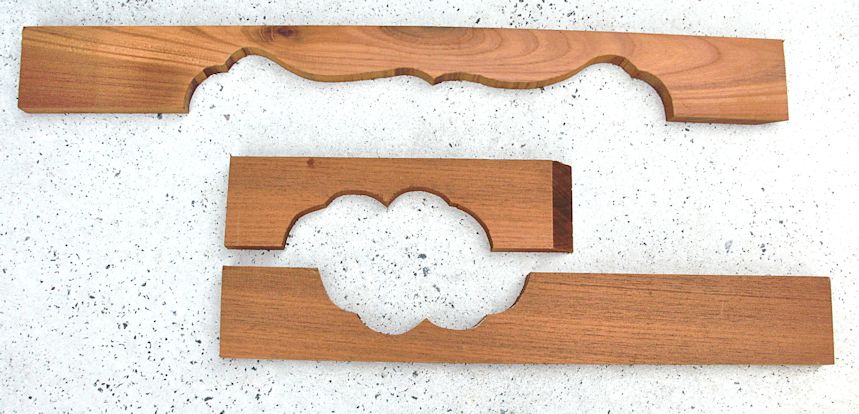
A backing panel was cut for the base and this was to fit between the sides. Well-figured edge-banding strips were cut to go around the feature base panel. These would also cover the visible join between the side and the front panel. A decorative shaped plinth molding was cut out to finish the base, figure 4, and finally a small concave moulding was made on the router to cap the shaped plinth.
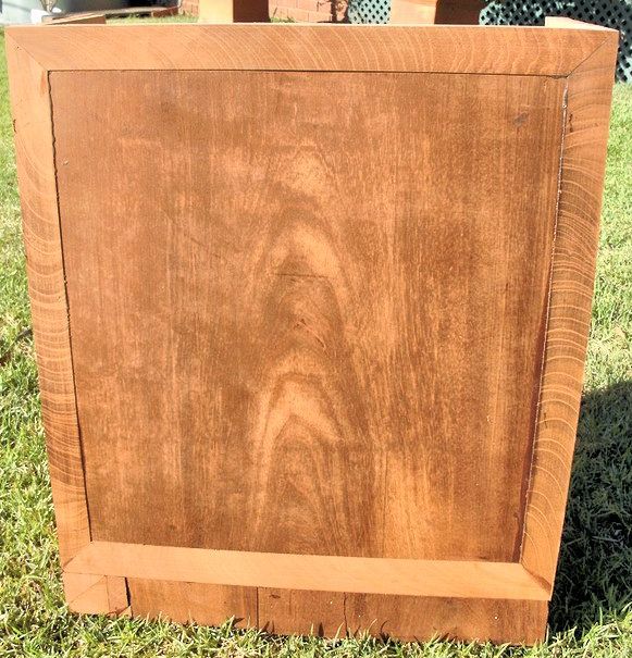
To assemble the base I first attached a section of scrap cedar panel to the inside of each base side. I left a gap at the front edge against which I would seat the front backing panel of the base front. At the rear I left a gap against which I would seat the back of the case. These were glued and nailed into place.
I marked out and glued the feature panel to the base front allowing for a 30mm banding strip to edge the panel. I had also to make allowance for the plinth moylding to be attached to the base. When this was completed the base was set to one side, figure 5.
A section of backing cedar was chosen for the trunk door and this was cut to size and shape. The feature panel was sized and shaped accordingly with the top contour mirroring that of the backing board.
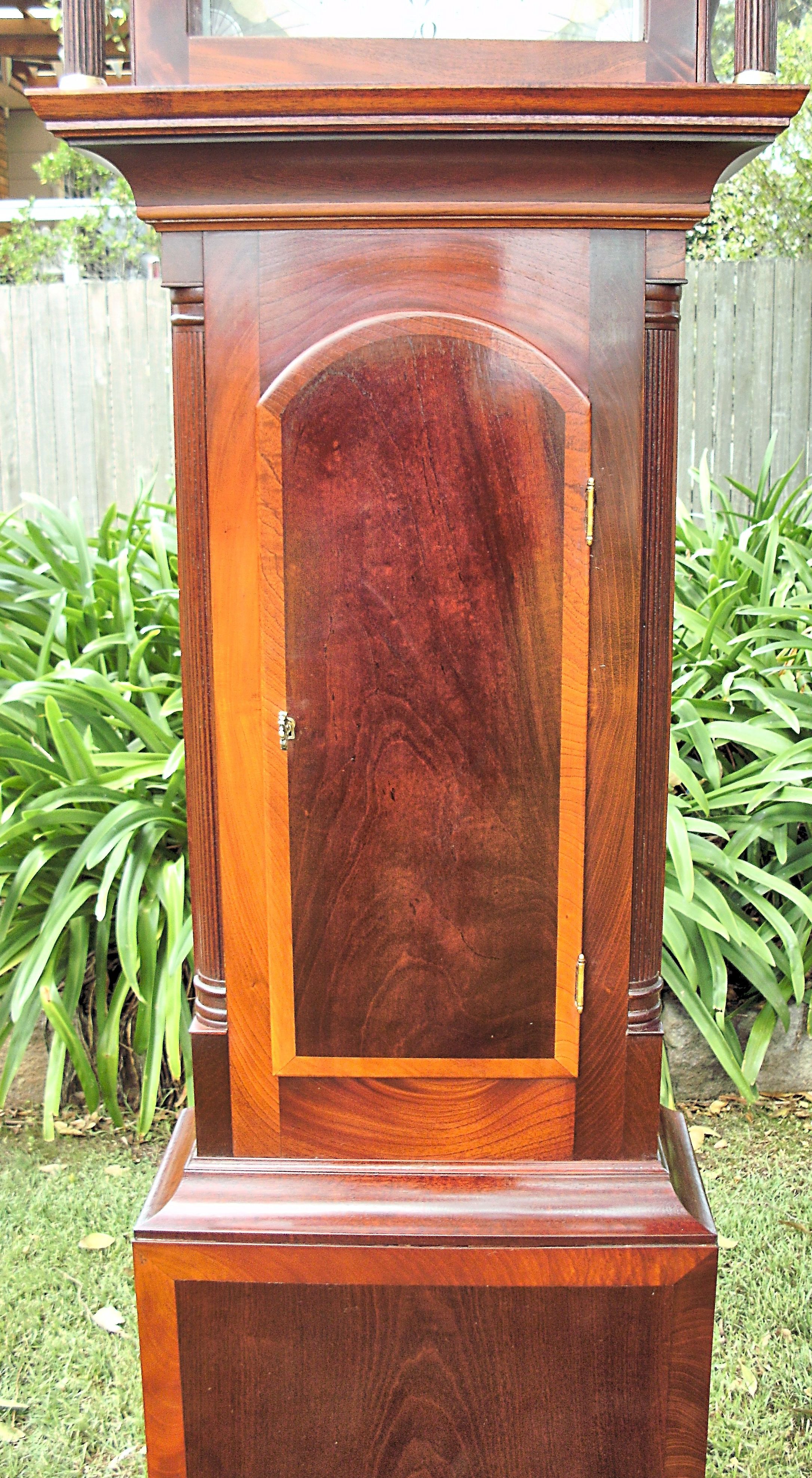
The edge banding was cut to shape and applied to the door in such a way as to leave a 4mm overhang around the door, figure 6.

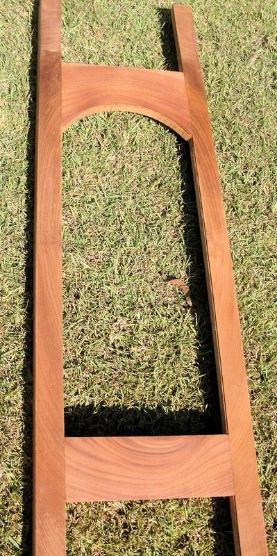
Measurements were made for the stiles and cross rails of the trunk and timber selected that would give the appearance of grain flow around the door. The trunk front was then assembled, figure 7. As quartered reeded columns were to be applied down each side of the trunk it was necessary a void be formed along the stiles that would accommodate them.
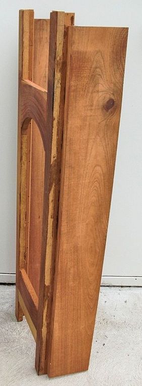
To achieve this a 40mm wide timber strip 10mm thick was glued along the inner face edge of the trunk sides. A similar 30mm wide strip would be fixed behind the outer edge of the stiles. When the stiles were fixed to the sides a 30mm void would be when 10mm of the strip on the side would be taken up when the stile was seated against the sides, figure 8.
Incised fillets were fixed along the inner front and sides of the base and the trunk was joined to the base. The fillets take up the space between the inner top edge of the base and the outer edge of the trunk. They also serve as the platform upon which the base mouldings will seat.
It was now time to tackle a few of the more time-consuming challenges of the case build. I needed to construct the reeded quarter trunk columns, as well as their capitals and bases and I also had to make the concave trunk mouldings.
Four sections of straight-grained early dark grained cedar were cut 33mm square. These were spot glued together with strips of paper between each surface. A capping piece was glued at each end. When dry this 66mm square block was to be turned on a lathe to finish 60mm round.
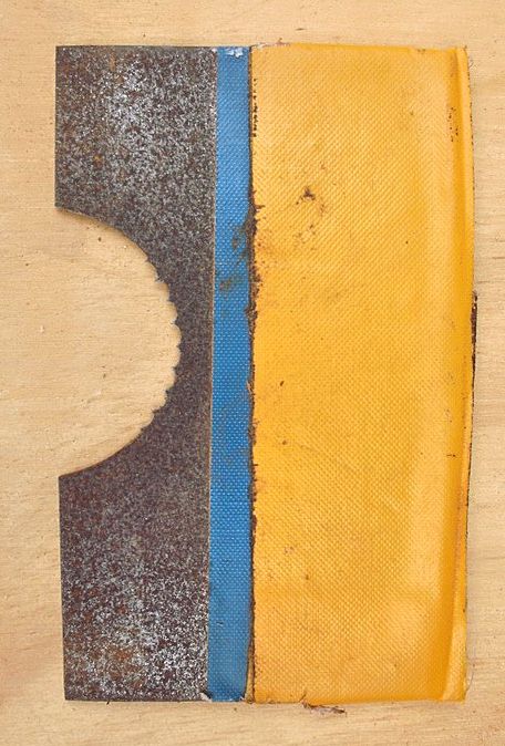
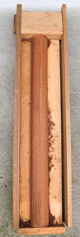
I have constructed a special reeding scraper, figure 9, and a jig box that holds secure the split turned rounded section while it is being reeded, figure 10. The scraper fits snugly between the sides of the jig box. The rounded section sits approximately 2.5mm higher than the scraper’s lowest point. By patiently drawing the scraper along the face of the rounded cedar section grooves are formed. The block is then rotated a few degrees and the process repeated making very sure the grooves of the scraper match up with the grooves being scraped along the wood.
When completed the end caps are removed and a paint scraper inserted along the papered join and the rounded section separated into its four parts. The best two sections are chosen and these are finished with a V-file and fine grit paper.
A similar split turning procedure is used to form the capitals and bases for the quarter columns. The only difference is that these are turned to the desired shape before being cut to length and separated, figure 11.
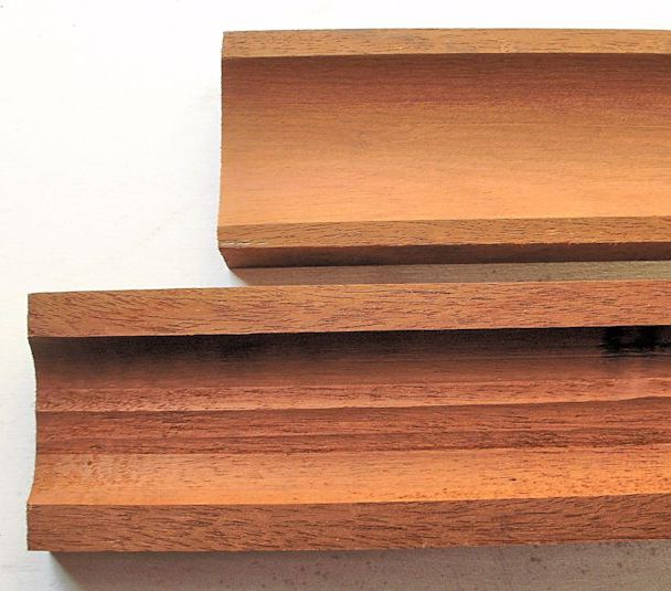
Two lengths of figured cedar 50mm wide and 25mm thick were chosen to construct the concave trunk moldings. In turn each length was passed over a convex cutter mounted in my router bench. The length was then turned end to end and the procedure repeated, figure 12.
I used a section of brass pipe and diminishing grades of sand paper to ensure a perfect concavity along each moulding length, figure 12. Then by setting the blade on my bench saw to a 45-degree angle I passed each section between blade and guide along each edge to achieve the 90-degree angles necessary to form up the moulding, figure 11. A smaller length of concave capping moulding was shaped on the router to seat upon the top edges of the concave base moulding.
Before fitting the concave base mouldings I had to glue in the trunk corner blocks that seat the capitals and bases for the reeded quarter columns. These fill the void above and below the feature columns. Again they are a feature and should be made from well-grained timber. The blocks sit very slightly proud of the side and trunk front. There is a thin cap wooden that sits slightly proud at the top of each block upon which the capital or base seat.

I was now able to mitre the finished concave moldings and attach them around the trunk top and base to complete the assembly of the lower section of the new case. I attached the trunk door to which I had fitted a lock and hinges and once done I gave the case three coats of shellac.
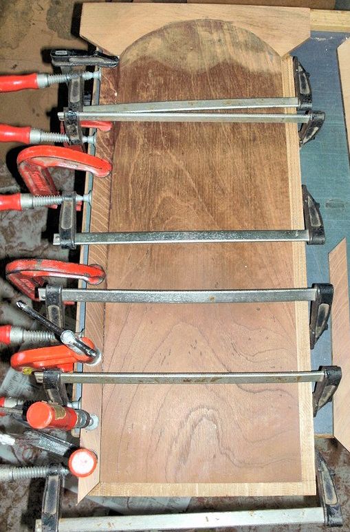
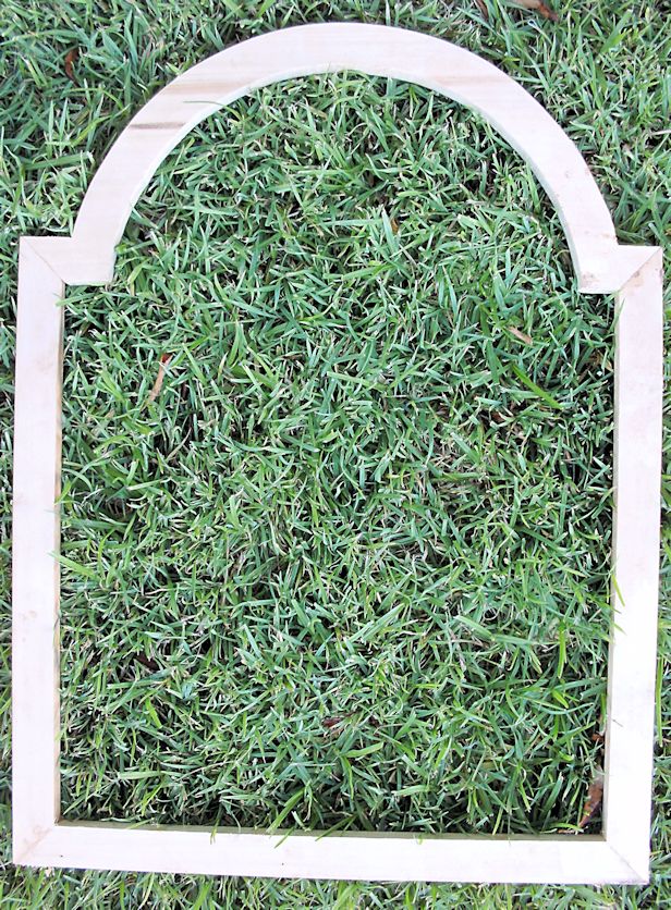
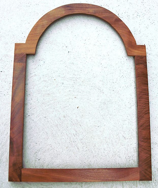
The hood construction commenced with the construction of the door. A template of the dial was made and was used as a guide to ensure that the door would be the correct shape. Timber 25mm wide and 12mm thick was mitered and made to go around the dial template. This was glued together, figure 13. I then ran a cut into each corner on my bench saw and glue a cedar wafer into each cut to afford added strength to the frame.
I overlaid the frame with a 5mm thick cedar veneer that is 30mm wide. This veneer is flush with the outer edge of the frame and it forms a rebate on the inner face that will serve as the seat for the glass. The veneer is then sanded smooth, figure 14, and the door set to one side.
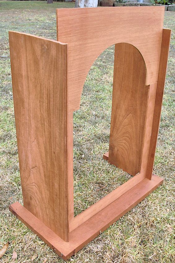
I formed up the base of the hood and before attaching the hood sides I ran a very small fancy bead along the leading edge of both. The case was designed to have the hood door fit between the sides so a notch was cut into the bottom of each side panel so that it protruded onto the front rail of the base, figure 15.
The dial mask was constructed from 5mm thick cedar. I make the mask up to 6mm smaller than the actual dial. To seat the dial behind the mask I use a router cutter to cut a 3mm wide channel 2mm deep along the rear inner edge of the mask. The top of the mask will seat against the rear of the hood arch that is constructed to accommodate the break arch of the hood door.
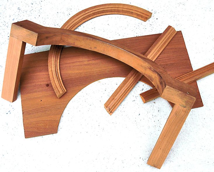
I cut the top hood arch section out of 35 mm scrap cedar and to it I attached the side soffits, figure 16. Two further sections required construction with the same profile as the hood door break-arch.
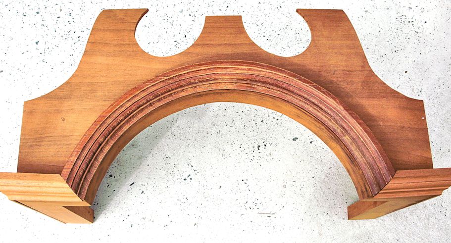
The easier of the two was the crest fascia and this was soon completed. A more difficult task was to construct the hood arch moulding. This was done on the router table and then cut to size.
I always construct the top of the hood as a unit before I attach it to the hood. To do this I had to fix the side fascia against the soffits and butt the front fascia against the leading edge of the sides. Next the mouldings were fitted around the fascia, figure 17.
With all case builds there numerous rather fiddly steps that need to be undertaken. A great deal of time is spent adjusting and sanding to achieve the finish desired.
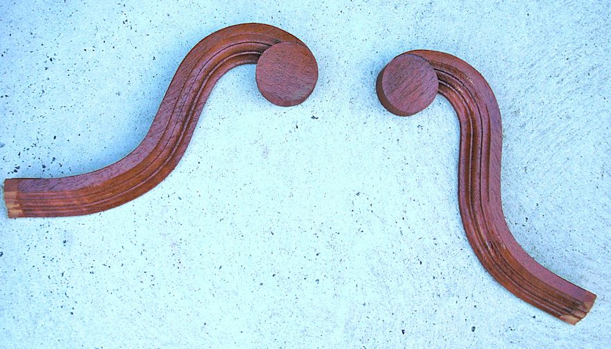
I had made an outline of the swan pediments that I wished to have on the case. The shape was drawn on to 25mm thick cedar and the bottom section cut to shape on the band saw. This was passed carefully over a router cutter to achieve the desired profile. At the same time an extra length with the same profile was made for the side moldings. The shaped profiles were then carefully sanded smooth to finish. A scribe was used to mark the depth required and the top edge cut to shape.
Two 55mm cedar rounds were cut out of the same timber and sanded. I scribed an arc of the same diameter as the round to the rear peak of the swan neck and I cut to this line with a jeweler’s saw. The rounds were glued into place to form the swan necks, figure 18a.


The swan necks were carefully positioned on the crest fascia and pencil lines drawn in preparation for finally cutting the fascia to shape. The swan necks and the side mouldings were cut to length and fitted to the sides of the top.
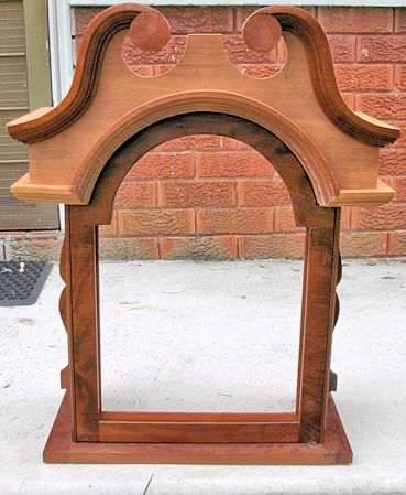
When the top had been fixed permanently into place on the hood, figure 18b, I cut, shaped and fitted the side splats. I attached the hinges for the hood door and cut and fitted wavy old glass in the door. I fitted a period style moulding I had routered around the base of the hood.
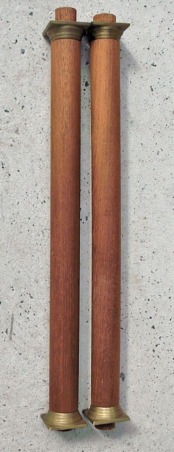
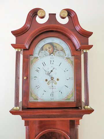
Hood pillar blanks were turned out of dark straight-grained cedar and fitted with brass capitals and bases I had purchased from the UK, figure 19. I used a similar method of reeding these columns with a purpose-made metal scraper and a purpose made jig box. When the columns were finished to my satisfaction I attached them to the case, figure 19b.
I chose to use the back of the original case as the new back so keeping some of the old with the new. It had to be reduced in thickness and it turned out to be ideal for the job.
The case was given several coats of shellac then rubbed back with steel wool. Several generous coats of wax were applied over the following days with a vigorous buffing between each application, figures 20 and 21.
The restored Samuel Brown movement with its freshened-up painted dial was carefully fitted to the new case and its owner summonsed to see the completed project, figures 22 to 24.
Mr Brown now sits in pride of place in its new home and I am almost certain that I did see a tear of joy trickle from the corner of Belinda’s eye when she first saw her treasured clock resplendent in its new cedar case.
Download a pdf of this article
|
|

